The BlueDot BME680 Environmental and Gas Sensor not only allows you to measure temperature, humidity, pressure, and altitude with an Arduino, but with the integrated Metal Oxide (MOX) Gas Sensor you can measure volatile organic compounds (VOCs) in the air. The Metal Oxide-based sensor detects VOCs by adsorption on its sensitive layer and its resistance changes with the VOC concentration (the higher the VOC concentration, the lower the output resistance and vice-versa). As a result, the raw signal is a resistance value in ohms.
Volatile organic compounds are typically found in building materials, printers, solvents, paints, gasoline, and many household products. Long-term exposure to VOCs can be harmful to our health and since we spend so much time indoors (homes and offices), it is important to find the source and reduce the concentration of VOCs in indoor environments.
Now let’s get started with the BlueDot BME680 and take our first steps with this environmental sensor.

Description
Here are five features that make the BlueDot BME680 Environmental and Gas Sensor very easy to use:
- Temperature, Humidity, Pressure, and Altitude Measurements. You can measure temperature, relative humidity, and air pressure with high precision. Besides, the pressure measurements allow you to calculate your altitude with a precision of ± 1.0 meters.
- Measurement of VOC Concentration. You can detect high concentrations of VOCs in the surrounding air. The raw signal is a resistance value in ohms, which goes down with increasing VOC concentration.
- 3.3V and 5V Power Supply. The onboard voltage regulator accepts anything from 2.6V to 5.5V to supply the BME680 sensor.
- SPI and I²C Communication. Depending on your project, you may choose between SPI and I²C protocols to communicate with the sensor.
- Data Transfer with 5V and 3.3V devices. While devices like the Arduino Uno interpret a 5V signal as a logic HIGH, the BME680 uses 3.3V as a logic HIGH. The onboard logic level converter translates the 5V signals into 3.3V signals and vice-versa.
This quick start guide on the BlueDot BME680 will show you how to take the first steps with this environmental sensor board.
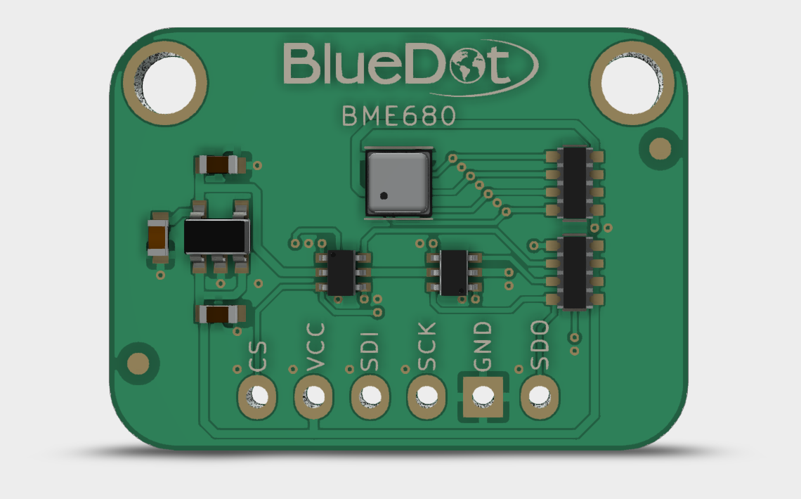
Assembly
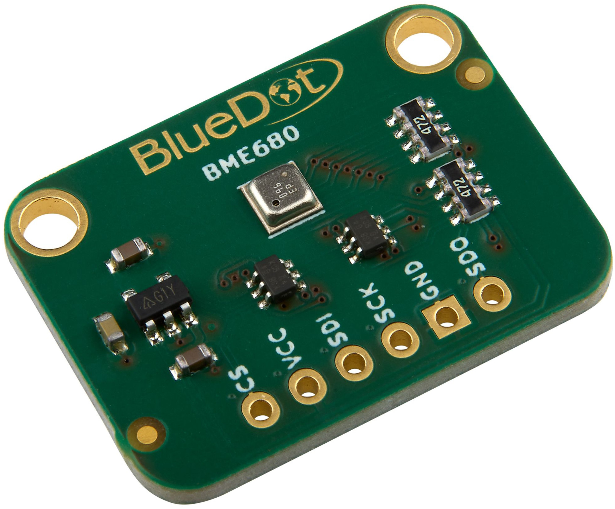
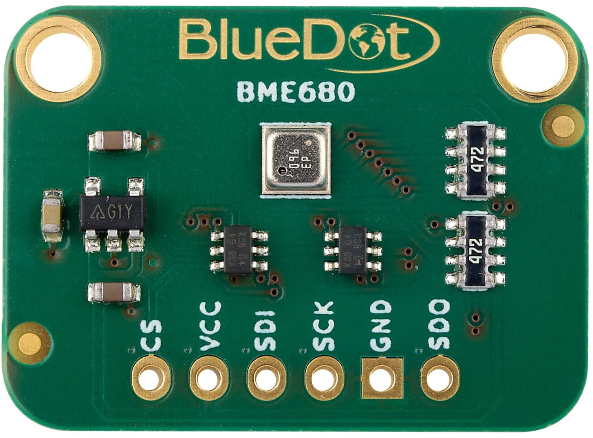
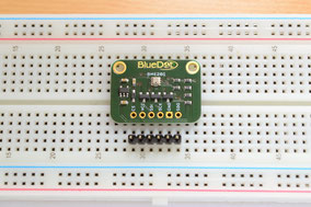
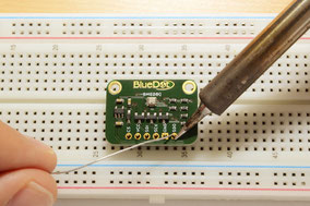
The first step with the BME680 Weather Station is to solder the 6-pin header that comes along with the board. The easiest way to solder the board is to insert the header into a breadboard (long pins down) and solder the short pins to the board.
Connecting to ESP8266 via I²C
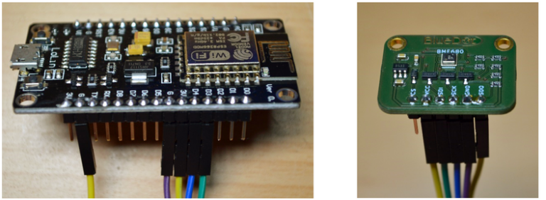
Connecting the BME680 to an ESP8266 WiFi microcontroller allows you to measure the IAQ index with the BSEC library. Take a look at our tutorial section for a complete guide on how to do that!
Connecting via I²C
Connecting the BME680 to the I²C bus is very easy and is identical to the connection of the BME280 sensor. The first step is to connect the board to the power supply.
- VCC Pin. Connect the VCC pin from the board to either 5V or 3.3V output from your Arduino.
- GND Pin. Connect the GND pin from the board to the GND from the Arduino.
Great! Now we need to connect the sensor to the I²C bus. The I²C communication uses two wires. The clock signal is generated by the Arduino and transferred to the sensor through the SCL line. On the other hand, the Arduino can send commands to the sensor using the SDA line. Just as well, all data from the sensor goes back to the Arduino through the SDA line. Because of that, the SDA line is bidirectional.
- SDI Pin. Connect the SDI pin from the board to the SDA line on the Arduino. This corresponds to the pin A4 on the Arduino Uno.
- SCK Pin. Connect the SCK pin from the board to the SCL line on your Arduino. This corresponds to the pin A5 on the Arduino Uno.
- SDO Pin. Here we have two options. Leave the SDO pin unconnected to use the default I²C address (0x77). Instead, we can connect the SDO pin to GND to use the alternative I²C address (0x76).
- CS Pin. Leave it unconnected.

Connecting via Hardware-SPI
We can also communicate with the BME680 sensor using the SPI protocol. Just like before, the first step is to connect the board to a power supply.
- VCC Pin. Connect the VCC pin from the board to either 5V or 3.3V output from your Arduino.
- GND Pin. Connect the GND pin from the board to the GND from the Arduino.
Unlike the I²C protocol, SPI communication uses four different lines. All data from the sensor is transferred back to the Arduino through the SDO line (Serial Data Output), while all commands from the Arduino are transferred through the SDI (Serial Data Input) line. The clock signal is generated from the Arduino and sent through the SCK line (Serial Clock). Finally, the CS or Chip Select line is used to tell the sensor when the communication is starting or ending.
- SDI Pin. Connect the SDI pin from the board to the MOSI pin on the Arduino. The MOSI pin (Master Out Slave In) is located on the ICSP header.
- SCK Pin. Connect the SCK pin from the board to the SCK pin on your Arduino. You will also find the SCK pin on the ICSP header.
- SDO Pin. Connect the SDO pin from the board to the MISO pin on the Arduino. The MISO pin (Master In Slave Out) is also located on the ICSP header.
- CS Pin. Connect the CS pin from the board to the digital pin 10 on the Arduino. If you like, you can use any other digital pin, just remember to change the program as well.

Not sure where the ICSP header is located? On the Arduino Uno, it is the header on the far side of the board, close to the microcontroller.

Connecting via Software-SPI
We can also use the SPI communication without using the ICSP header, using regular digital pins instead. In this case, the communication is called Software-SPI.
- VCC Pin. Connect the VCC pin from the board to either 5V or 3.3V output from your Arduino.
- GND Pin. Connect the GND pin from the board to the GND from the Arduino.
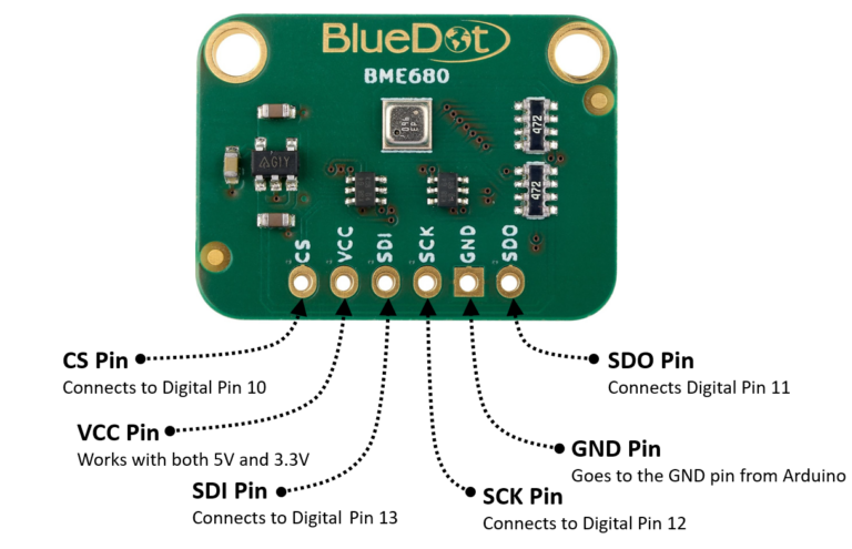
- SDI Pin. Connect the SDI pin from the board to the digital pin 13 on the Arduino.
- SCK Pin. Connect the SCK pin from the board to the digital pin 12 on the Arduino.
- SDO Pin. Connect the SDO pin from the board to the digital pin 11 on the Arduino.
- CS Pin. Connect the CS pin from the board to the digital pin 10 on the Arduino.
Installing Arduino Library
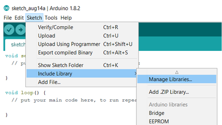
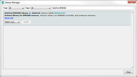
The BlueDot BME680 board works best with the Arduino Library written by Adafruit. The easiest way to start using your BME680 sensor is to download and install the library directly from the Arduino IDE. Just open the Arduino IDE and go to Sketch > Include Library > Manage Libraries… and search for the Adafruit BME680 Library on the Library Manager. Alternatively, you can download the latest version of the library from their Github repository.
Upload Example-Sketch
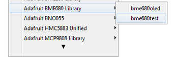
After installing the library we can open an example sketch. Adafruit included a great example, which we can use to run the BME680. Just go to File > Examples > Adafruit BME680 Library and open the sketch bme680test.
Now let’s take a look at the example sketch. The first step in the program is to define the communication protocol. Depending on how you connected the board to the microcontroller, choose between I²C, Hardware SPI, and Software SPI. The default value is set to the I²C mode.
   Adafruit_BME680 bme; // I2C
 //Adafruit_BME680 bme(BME_CS); // hardware SPI
 //Adafruit_BME680 bme(BME_CS, BME_MOSI, BME_MISO,  BME_SCK);
If you are using the Hardware SPI mode, then you need to write into the program, which digital pin is connected to the CS pin of the BME680. If you are using the Software SPI mode, then you also need to define digital pins for the MISO (SDO), MOSI (SDI), and SCK pins. These can be defined at the very beginning of the sketch.
    #define BME_SCK 13
    #define BME_MISO 12
    #define BME_MOSI 11
    #define BME_CS 10
This is all you need to do before running the program. But before doing so, you have the option of adjusting the oversampling factors and the IIR filter (Infinite Impulse Response), as well as the temperature of the internal heating plate and the heating duration for the gas measurements. The default values work great.
  //Set up oversampling and filter initialization
    bme.setTemperatureOversampling(BME680_OS_8X);
    bme.setHumidityOversampling(BME680_OS_2X);
    bme.setPressureOversampling(BME680_OS_4X);
    bme.setIIRFilterSize(BME680_FILTER_SIZE_3);
    bme.setGasHeater(320, 150); // 320*C for 150 ms
Now you are ready to run the sketch. What can you expect to receive from the BME680 sensor?
Like the BME280 sensor, the BME680 measures temperature, humidity, atmospheric pressure, and altitude (calculated from the air pressure). The BME680 also contains an integrated metal oxide gas sensor, which works as a hot plate with an electrical resistance that decreases when exposed to certain gases in the atmosphere. The sensor heats the hot plate to the target temperature for a certain duration (default values are 320°C for 150 ms) and after that, it measures the electrical resistance of the hot plate. As a result, this electrical resistance is the output of the gas sensor.
3D Model
A 3D model of the BlueDot BME680 board is available as a STEP file (click here to download). A STEP file is a CAD file format widely used for exchanging CAD files between companies and can be easily read by most (if not all) CAD software applications.
You can also view 3D models online without installing any software on your computer. The images below were taken using Autodesk Viewer, an online, free-to-use tool from Autodesk. It does require registration at Autodesk, but it is worth it!
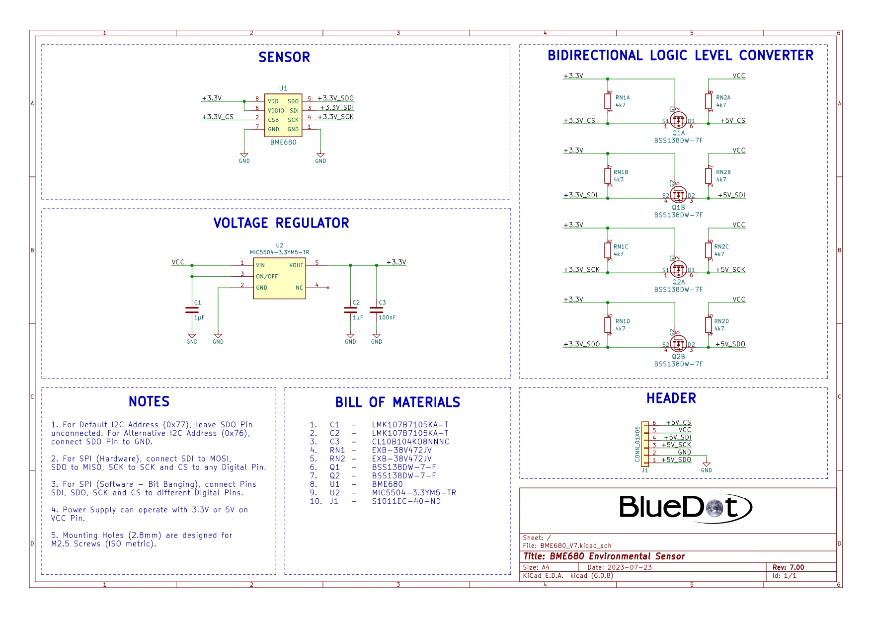
Schematics