
The BNO055 absolute orientation sensor is an amazing device. It integrates an accelerometer, a gyroscope, and a 32-bit microcontroller in a single package. Not only can you read the sensors simultaneously, but a fusion algorithm running on the onboard microcontroller analyzes all the measured data and calculates the orientation of the device in space.
It can be distinguished between non-absolute or relative orientation and absolute orientation. Absolute orientation means the orientation of the sensor to the earth and its magnetic field. In other words, absolute orientation sensor fusion modes calculate the direction of the magnetic north pole. In non-absolute orientation modes, the heading of the sensor can vary depending on how the sensor was placed initially.
Now let’s get started with the BlueDot BNO055 and take our first steps with this orientation sensor.


Description
Here are five features that make the BlueDot BNO055 9-Axis IMU such a fantastic board:
- Magnetic Field, Acceleration, and Angular Rate. The BNO055 contains a triaxial geomagnetic sensor, a triaxial 16-bit gyroscope, and a triaxial 14-bit accelerometer in a single package. This enables you to simultaneously measure linear acceleration, rotational acceleration, and the strength of the magnetic field.
- Fusion Modes. The fusion algorithm running on the onboard 32-bit microcontroller reads all the sensors simultaneously. It delivers valuable data like the gravity field vector, the device’s absolute orientation (through the quaternions and Euler vectors), the magnetic north (as with a compass), etc.
- 3.3V and 5V Power Supply. The onboard voltage regulator accepts anything from 2.6V to 5.5V to supply the BME280 sensor.
- I²C Communication. Using the I²C protocol you need no more than two wires to communicate with the BNO055 sensor.
- Data Transfer with 5V and 3.3V devices. While devices like the Arduino Uno interpret a 5V signal as a logic HIGH, the BNO055 uses 3.3V as a logic HIGH. The onboard logic level converter translates the 5V signals into 3.3V signals and vice-versa.
This quick start guide on the BlueDot BNO055 will show you how to take the first steps with this orientation sensor board.
Important Note
The sensors TSL2591 and BNO055 do not work together. They share the same I²C addresses (0x28 and 0x29). Despite using only the address 0x29 for the I²C communication, the sensor TSL2591 also reserves the address 0x28 all the time. If you wish to use the BME280+TSL2591 board with the BNO055 board, please consider using an I²C multiplexer.
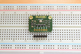
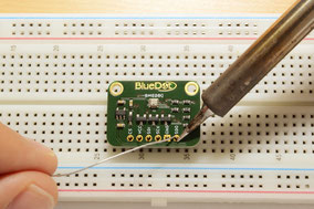
Assembly
Along with the BlueDot BNO055 Board you also get a 10-pin header to connect the sensor. The easiest way to solder the board is to insert the header into a breadboard (long pins down) and solder the short pins down.
Connecting via I²C
The BlueDot BNO055 IMU Board is hardwired to use the I²C communication protocol. The first step to using the sensor is to connect the board to a power supply.
- VCC Pin. Connect the VCC pin from the board to either 5V or 3.3V output from your Arduino.
- GND Pin. Connect the GND pin from the board to the GND from the Arduino.
- 3V3 Pin. The 3V3 pin is connected directly to the output from the voltage regulator and you can use it to supply an external load. The maximum output current of the regulator is 150 mA, but just to be safe, avoid taking more than 50 mA from it.
Connecting the sensor to the I²C bus is very easy. For that, you need only two wires. The clock signal is generated by the Arduino and transferred to the sensor through the SCL line. The Arduino can send commands to the sensor using the SDA line. Just as well, all data from the sensor goes back to the Arduino through the SDA line. Because of that, the SDA line is bidirectional.
- SDA Pin. Connect the SDA pin from the board to the SDA line on the Arduino. This corresponds to the pin A4 on the Arduino Uno.
- SCL Pin. Connect the SCL pin from the board to the SCL line on your Arduino. This corresponds to the pin A5 on the Arduino Uno.
- ADR Pin. Here we have two options. Leave the ADR pin unconnected to use the default I²C address (0x28). Instead, we can connect the ADR pin to 3.3V to use the alternative I²C address (0x29).
That is all! You can leave the other pins unconnected and you are good to go! But what about the other pins, you may be wondering?
- INT Pin. You can program the BNO055 to trigger an interrupt signal whenever a certain event occurs. For example, you can trigger an interrupt when the accelerometer detects a high-g movement or when the gyroscope detects a sudden change in the angular rate. You can find a full description of the possible interrupts on the datasheet (pages 38 to 46).
- RST Pin. By applying a LOW signal and then a HIGH signal to the RST pin you trigger a power-on reset. This forces the sensor to restart in CONFIG mode and it initializes the register map with all default values.
- PS0 and PS1 Pins. These pins can be used to change from I²C mode to HID (Human Interface Device) protocol. In case you are only using the I²C mode, just leave them unconnected.

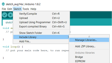
Installing Arduino Library
The BlueDot BNO055 board works great with the Arduino Library written by Adafruit. The easiest way to start using the BNO055 IMU is to download and install the library directly from the Arduino IDE. Just open the Arduino IDE and go to Sketch > Include Library > Manage Libraries… and search for the Adafruit BNO055 Library on the Library Manager.

Upload Example-Sketch
After installing the library we can open an example sketch. Adafruit included a great example, which we can use to run the BNO055 IMU. Just go to File > Examples > Adafruit BNO055 Library and open the sketch rawdata.

Now upload the example sketch to your microcontroller and you are good to go!

3D Model
A 3D model of the BlueDot BNO055 board is available as a STEP file (click here to download). A STEP file is a CAD file format widely used for exchanging CAD files between companies and can be easily read by most (if not all) CAD software applications.
You can also view 3D models online without installing any software on your computer. The images below were taken using Autodesk Viewer, an online, free-to-use tool from Autodesk. It does require registration at Autodesk, but it is worth it!

Schematics

