Home > Tutorials > Get started with the BlueDot VL53L1X
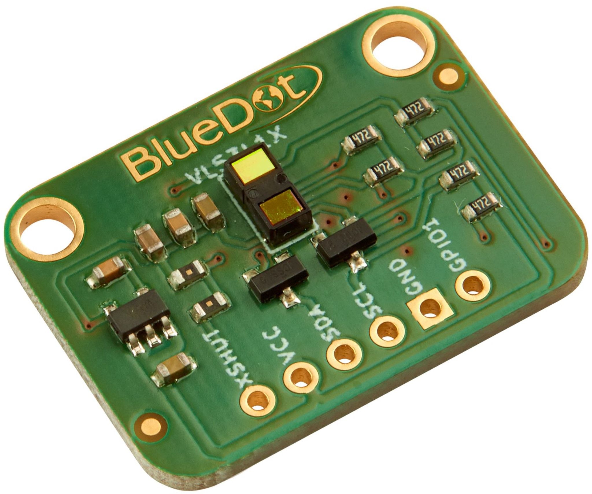
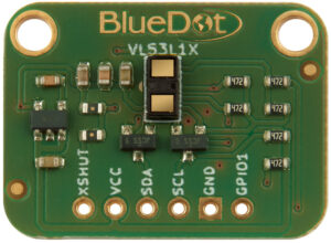
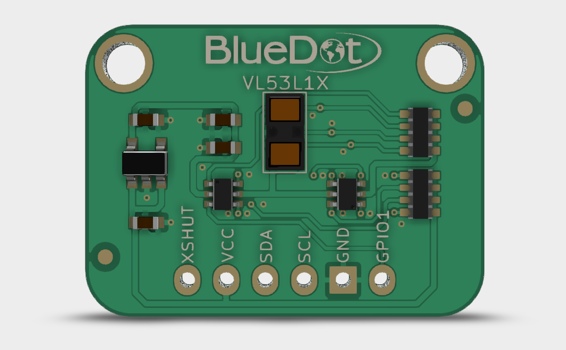
BlueDot VL53L1X Time-of-Flight Distance Sensor
The VL53L1X is a laser-ranging sensor from STMicroelectronics, capable of measuring distances up to 4 meters. It employs a 940-nanometer invisible laser beam (class 1 safety) and a SPAD photodetector (single-photon avalanche diode) to measure the time traveled by the laser beam between the sensor and the target. This technique is called Time-of-flight (ToF) and allows the calculation of the path traveled by the laser beam.
Now let’s get started with the BlueDot VL53L1X and take our first steps with this distance sensor.
Description
Here are the board’s main features:
Distance Measurements up to 4 m. Distance measurements are independent of ambient light conditions and target characteristics, like color, shape, or texture. These factors will influence the maximum distance capable of being measured. The minimum distance for accurate measurements is 4 cm.
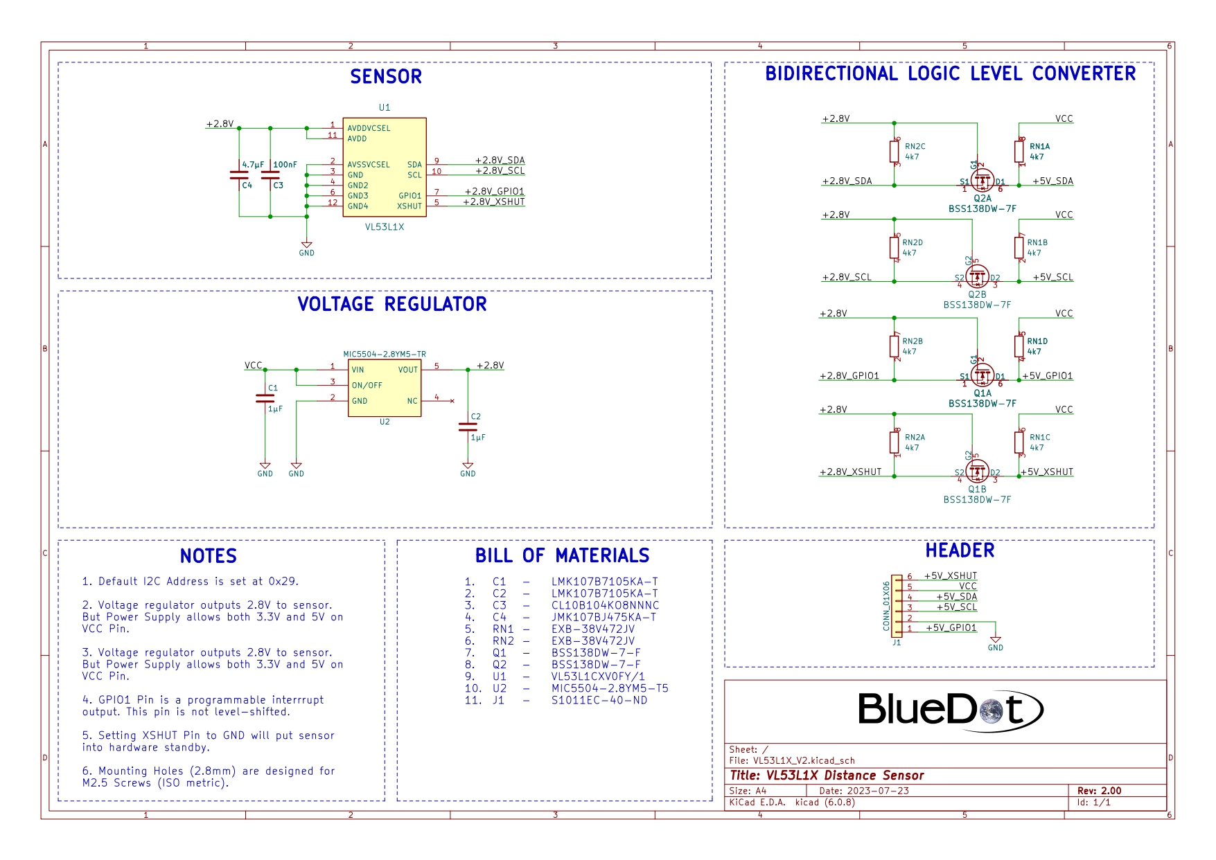
3.3V and 5V Power Supply. The onboard voltage regulator accepts anything from 2.6V to 5.5V to supply the VL53L1X sensor with a constant voltage of 2.8V.
I²C Communication. The sensor communicates through the I²C protocol using the address 0x29.
This quick start guide on the BlueDot VL53L1X will show you how to take the first steps with this Time-of-flight distance sensor.
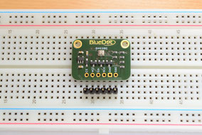
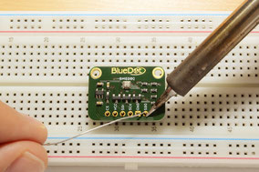
Assembly
The first step with the VL53L1X Distance Sensor is to solder the 6-pin header that comes along with the board. The easiest way to solder the board is to insert the header into a breadboard (long pins down) and solder the short pins to the board.
Finally, don’t forget to remove the protective film covering the sensor before using it, to guarantee proper sensor performance.
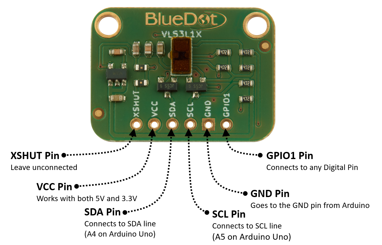
Connecting via I²C
Connecting the VL53L1X on the I²C bus is very easy. The first step is to connect the board to the power supply.
VCC Pin. Connect the VCC pin from the board to either 5V or 3.3V output from your Arduino.
GND Pin. Connect the GND pin from the board to the GND from the Arduino.
Great! Now we need to connect the sensor to the I²C bus. The I²C communication uses two wires. The clock signal is generated by the Arduino and transferred to the sensor through the SCL line. The Arduino can send commands to the sensor using the SDA line. Just as well, all data from the sensor goes back to the Arduino through the SDA line. Because of that, the SDA line is bidirectional.
SDA Pin. Connect the SDA pin from the board to the SDA line on the Arduino. This corresponds to the pin A4 on the Arduino Uno.
SCL Pin. Connect the SCL pin from the board to the SCL line on your Arduino. This corresponds to the pin A5 on the Arduino Uno.
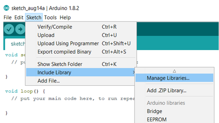
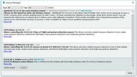
Although there is currently no Arduino Library from BlueDot available for this sensor, you can use the great library written by Pololu to connect to the VL53L1X. You can download and install the library directly from the Arduino IDE. Just open the Arduino IDE and go to Sketch > Include Library > Manage Libraries… and search for the Pololu Library on the Library Manager. You can find this library under the name “VL53L1X”. Alternatively, you can download the latest version of the library from their Github repository.
Upload Example-Sketch
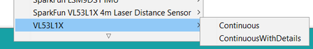
After installing the library we can open an example sketch. Just go to File > Examples > VL53L1X and open the sketch Continuous.
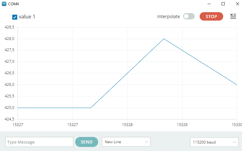
No changes are needed to run the sketch. Please note that the baud rate is set to 115200 per default. Here is the output visualized with the Serial Plotter from the Arduino IDE. In this case, the sensor is placed at a distance of 42 cm from a white wall.
A 3D model of the BlueDot VL53L1X board is available as a STEP file (click here to download). A STEP file is a CAD file format widely used for exchanging CAD files between companies and can be easily read by most (if not all) CAD software applications.
You can also view 3D models online without installing any software on your computer. The images below were taken using Autodesk Viewer, an online, free-to-use tool from Autodesk. It does require registration at Autodesk, but it is worth it!