
Connecting multiple BME280 sensors with SPI is just as easy as connecting a single sensor. Don’t believe it? In this tutorial, I will show you how to connect four BME280 sensors on the SPI bus. This is what you have to do:
- Connect the VCC pin from all four sensors to either the 5 V or the 3.3 V output from your Arduino.
- Connect the GND pin from all four sensors to the GND on the Arduino.
- Connect the SDI pin from all four sensors to the Digital Pin 13 on the Arduino.
- Connect the SCK pin from all four sensors to the Digital Pin 12 on the Arduino.
- Connect the SDO pin from all four sensors to the Digital Pin 11 on the Arduino.
As you can see, I am using regular digital pins to read and write to the sensor. In this case, I am using the Software-SPI communication.
But we’re not done yet. We now need to connect the Chip Select (CS) pin from each sensor to a different digital pin on the Arduino. Why different pins? Because each digital pin represents a different address, a way for the Arduino to know with which sensor he is talking. So, this is how we do it:
- Connect the CS pin from the first sensor to the Digital Pin 7 on the Arduino.
- Connect the CS pin from the second sensor to the Digital Pin 6 on the Arduino.
- Connect the CS pin from the third sensor to the Digital Pin 5 on the Arduino.
- Connect the CS pin from the fourth sensor to the Digital Pin 4 on the Arduino.

What about Hardware-SPI?
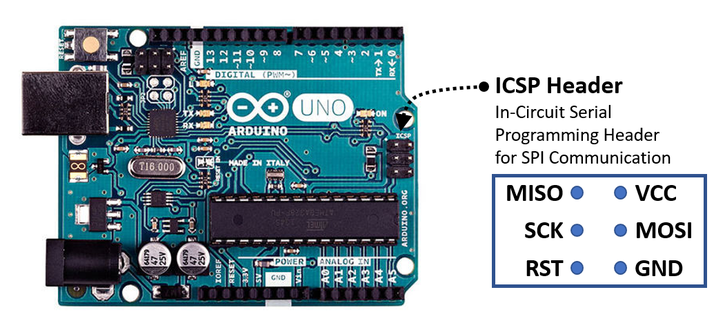
But we used a lot of digital pins for our communication! A different way to connect the sensors would be to connect the SDI, SCK, and SDO pins from the sensors to the ICSP header on the Arduino. That would be the Hardware-SPI communication:
- Connect the SDI pin from all four sensors to the MOSI pin on the ICSP header from the Arduino.
- Connect the SCK pin from all four sensors to the SCK pin on the ICSP header from the Arduino.
- Connect the SDO pin from all four sensors to the MISO pin on the ICSP header from the Arduino.
If you are anything like me, you also need some help finding out which ones are the MISO and the MOSI pins on the ICSP header!
Uploading Example Sketch for Multiple Sensors on SPI
Now we need the software. If you have not done this yet, download and install the BlueDot BME280 Library through the Arduino IDE. This library includes an example code with all you need to read multiple sensors on the SPI bus.
Go to Sketch -> Include Library -> Manage Libraries… and search for the BlueDot BME280 Library. Now click on it and install the library. You can also visit the GitHub repository to download the latest library version or click on this button below.
After installing the library, run the example for multiple sensors on the SPI bus. Just click on File -> Examples -> BlueDot BME280 Library -> BME280_MultipleSensorsSPI.

Setting up Example Sketch
The functions for each sensor are addressed by a different object, called bme1, bme2, bme3, and bme4. Now, the functions starting with bme1 refer to the first sensor, functions starting with bme2 refer to the second sensor, and the same goes for the third and fourth sensors.
    BlueDot_BME280 bme1;                                     //Object for Sensor 1
    BlueDot_BME280 bme2;                                     //Object for Sensor 2
    BlueDot_BME280 bme3;                                     //Object for Sensor 3
    BlueDot_BME280 bme4;                                     //Object for Sensor 4
The first step in the program is to choose between Software-SPI and Hardware-SPI. Set the parameter to 0 for Hardware-SPI or to 1 for Software-SPI. In this case, I am using Software-SPI.
    //0:                                                     //Hardware-SPI
    //1:                                                     //Software-SPI

      bme1.parameter.communication = 1; //Choose an SPI-Mode for Sensor 1
      bme2.parameter.communication = 1; //Choose an SPI-Mode for Sensor 2
      bme3.parameter.communication = 1; //Choose an SPI-Mode for Sensor 3
      bme4.parameter.communication = 1; //Choose an SPI-Mode for Sensor 4
The next step is to define a destination for the Chip Select (CS) pin from each sensor. I chose the digital pins 4, 5, 6, and 7.
  //Set the Chip Select pins for the SPI Communication.
  //Each sensor must have a different Chip Select pin.
  //Connect the Chip Select pins from the sensors to regular digital pins on the Arduino.

    bme1.parameter.SPI_cs = 4; //Chip Select Pin for Sensor 1
    bme2.parameter.SPI_cs = 5; //Chip Select Pin for Sensor 2
    bme3.parameter.SPI_cs = 6; //Chip Select Pin for Sensor 3
    bme4.parameter.SPI_cs = 7; //Chip Select Pin for Sensor 4
If you are using Hardware-SPI, then there is nothing else for you to do, just upload your code and read the sensors. But if you are using Software-SPI, you still need to define destinations for the SDI, SDO, and SCK pins.
  //Per default the MOSI line is on the pin 11, the MISO line on the pin 12 and the SCK line on the pin 13.
  //You may change those pins if you like, but remember to connect that pin to all sensors.

    bme1.parameter.SPI_mosi = 13; //The MOSI signal must be connected to the same pin for all sensors
    bme2.parameter.SPI_mosi = 13; //The MOSI signal must be connected to the same pin for all sensors
    bme3.parameter.SPI_mosi = 13; //The MOSI signal must be connected to the same pin for all sensors
    bme4.parameter.SPI_mosi = 13; //The MOSI signal must be connected to the same pin for all sensors
    bme1.parameter.SPI_miso = 11; //The MISO signal must be connected to the same pin for all sensors
    bme2.parameter.SPI_miso = 11; //The MISO signal must be connected to the same pin for all sensors
    bme3.parameter.SPI_miso = 11; //The MISO signal must be connected to the same pin for all sensors
    bme4.parameter.SPI_miso = 11; //The MISO signal must be connected to the same pin for all sensors
    bme1.parameter.SPI_sck = 12; //The SCK signal must be connected to the same pin for all sensors
    bme2.parameter.SPI_sck = 12; //The SCK signal must be connected to the same pin for all sensors
    bme3.parameter.SPI_sck = 12; //The SCK signal must be connected to the same pin for all sensors
    bme4.parameter.SPI_sck = 12; //The SCK signal must be connected to the same pin for all sensors
Now we are done! Here is an overview of the functions available for each sensor:
    Serial.println(bme1.readTempC());
    Serial.println(bme1.readTempF());
    Serial.println(bme1.readHumidity());
    Serial.println(bme1.readPressure());
    Serial.println(bme1.readAltitudeMeter());
    Serial.println(bme1.readAltitudeFeet());

    Serial.println(bme2.readTempC());
    Serial.println(bme2.readTempF());
    Serial.println(bme2.readHumidity());
    Serial.println(bme2.readPressure());
    Serial.println(bme2.readAltitudeMeter());
    Serial.println(bme2.readAltitudeFeet());

    Serial.println(bme3.readTempC());
    Serial.println(bme3.readTempF());
    Serial.println(bme3.readHumidity());
    Serial.println(bme3.readPressure());
    Serial.println(bme3.readAltitudeMeter());
    Serial.println(bme3.readAltitudeFeet());

    Serial.println(bme4.readTempC());
    Serial.println(bme4.readTempF());
    Serial.println(bme4.readHumidity());
    Serial.println(bme4.readPressure());
    Serial.println(bme4.readAltitudeMeter());
    Serial.println(bme4.readAltitudeFeet());
Finally, upload the code and open the Serial Monitor at a 9600 baud speed to read the temperature, humidity, pressure, and altitude from all four sensors.

